built my first series-parallel circuit:
* * *
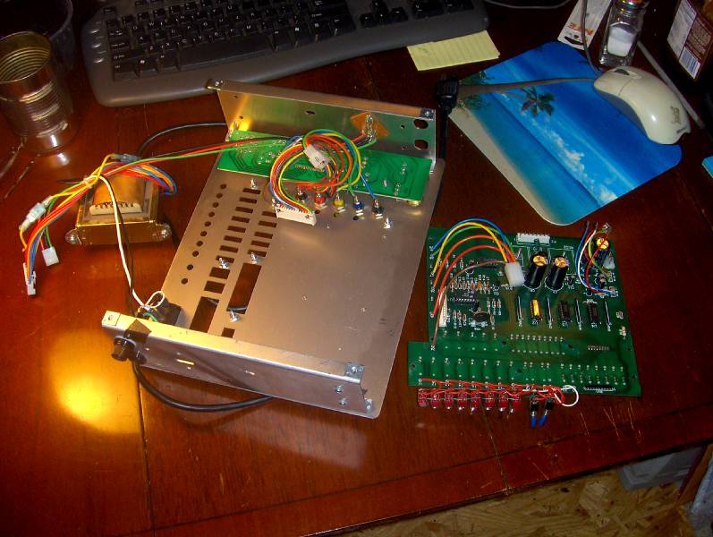
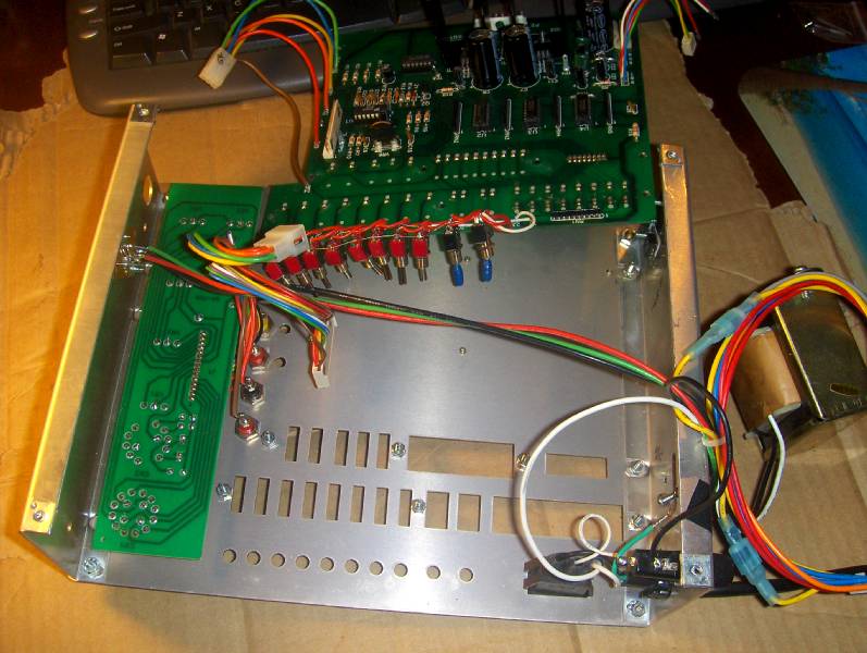
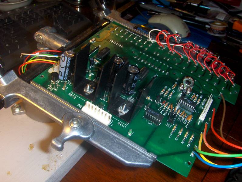
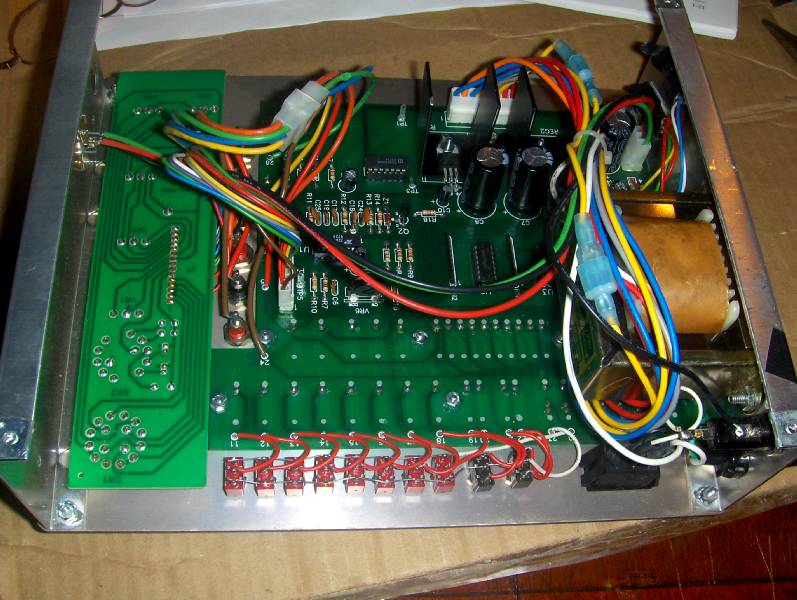
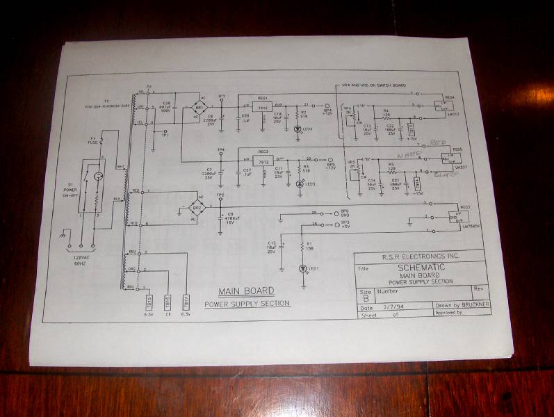
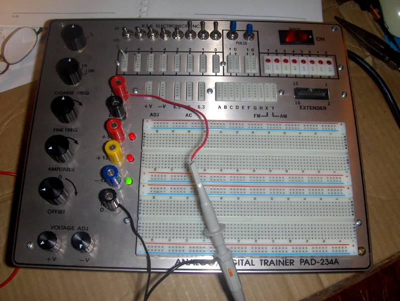
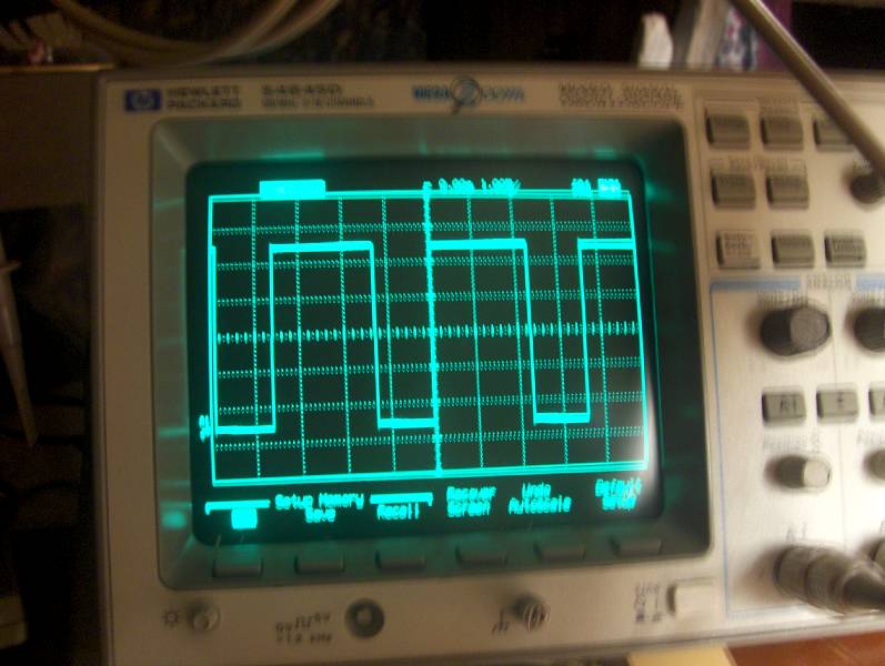
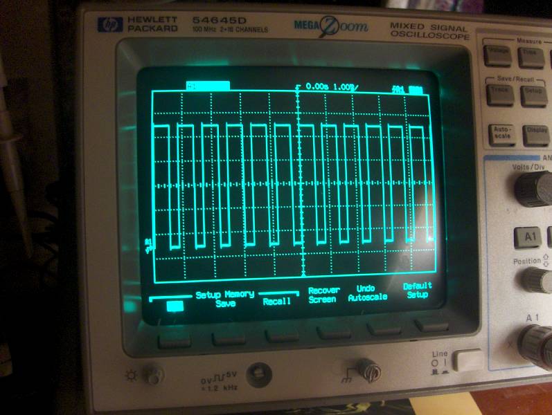
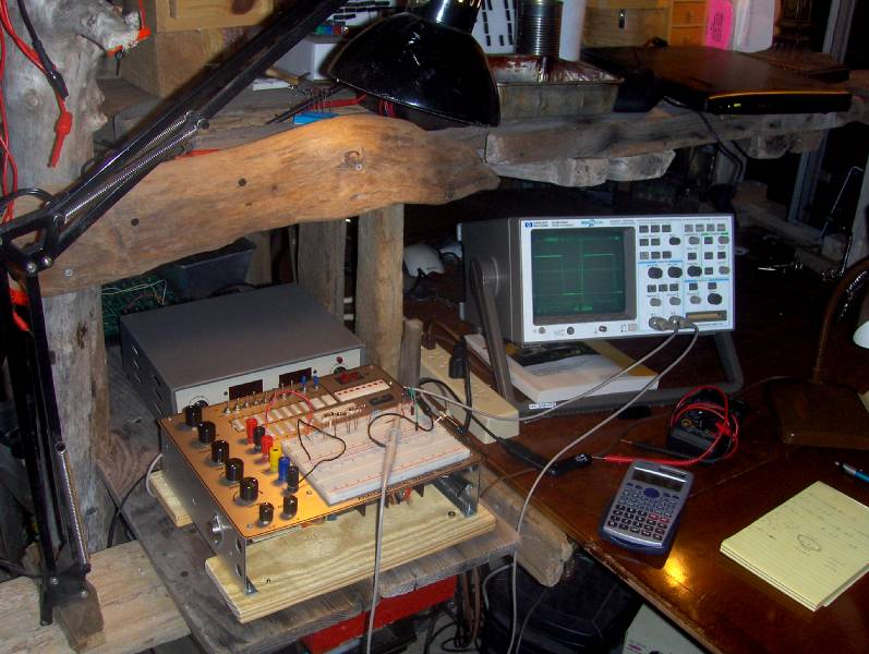
i bought this analog/digital trainer on ebay for $30. seemed like a good deal till i tried to use it and found that it just blew fuses. so i decided to try and fix it, i found and downloaded the schematic for it on the i-net while checking around with a meter to see if i could find anything obvious. i did not know what i was doing, but over the course of a month i took it apart more and more and learned a lot. i ordered and replaced voltage regulators a couple of times thinking i had it until i finally learned that it had a burned out bridge rectifier. basically what i would do was look at the schematic and try and isolate various circuits till it all started to make sense. there are a couple of pictures below of it taken apart, one of it in my solder station, another of it with the guts back together, the schematic of the power supply and finally one of it working. there are also two pics of it producing square wave pulses at different frequencies on my oscilloscope.
* * *
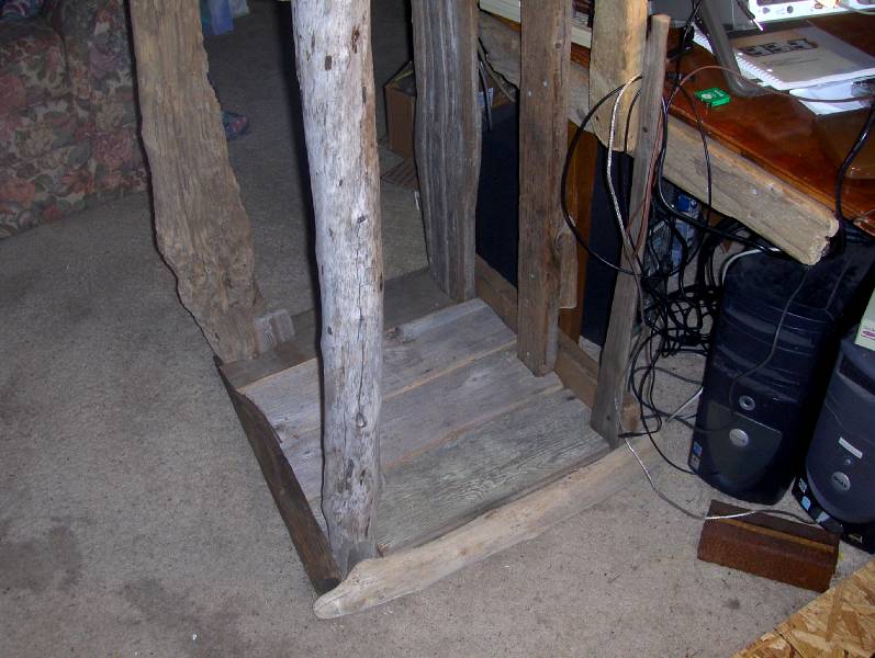
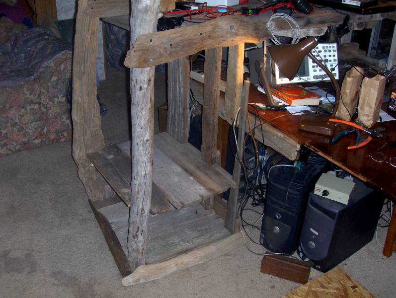
i am building an addition to my workstation out of driftwood. the area on the left will have shelves for all the electronics parts that i am acquiring for learning experiments and projects. i will include more pics as i add shelves.


* * *
the next few pics are of experimental circuits i have constructed for learning purposes that i want to save in some way before i pull all the pieces out of the bread board. the first two i want to save because i am proud of them. they are pics of what is called a ‘clamping circuit’ which i thought was a really cool idea on how one circuit can affect a second in a relationship sort of way. at first i had a hard time picturing it in my mind. but as i built it and made it work, i really got into it. the third pic is a test circuit i made to prove out an LM337 voltage regulator that went into the analog/digital trainer i fixed up above. by building this test circuit i was able to prove that the part was still good and therefore did not need replacing.
* * *
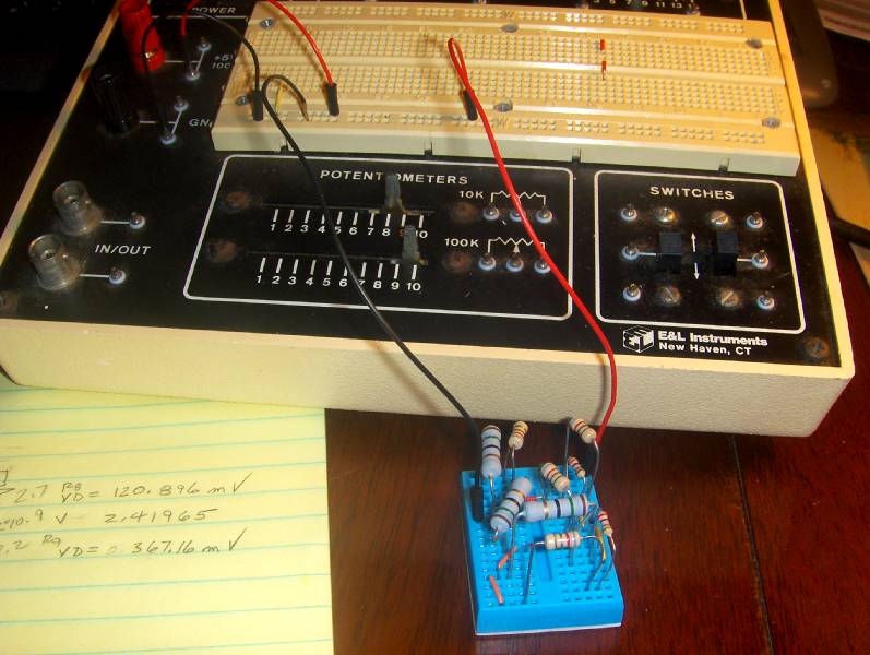
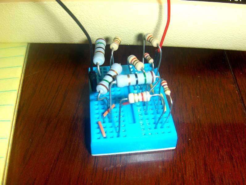
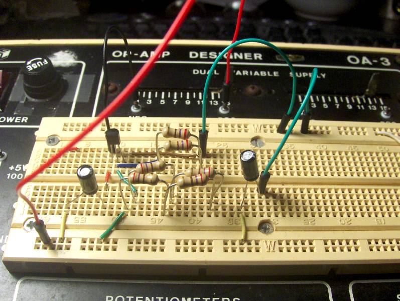
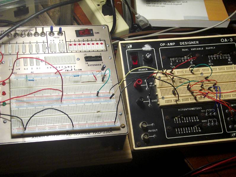
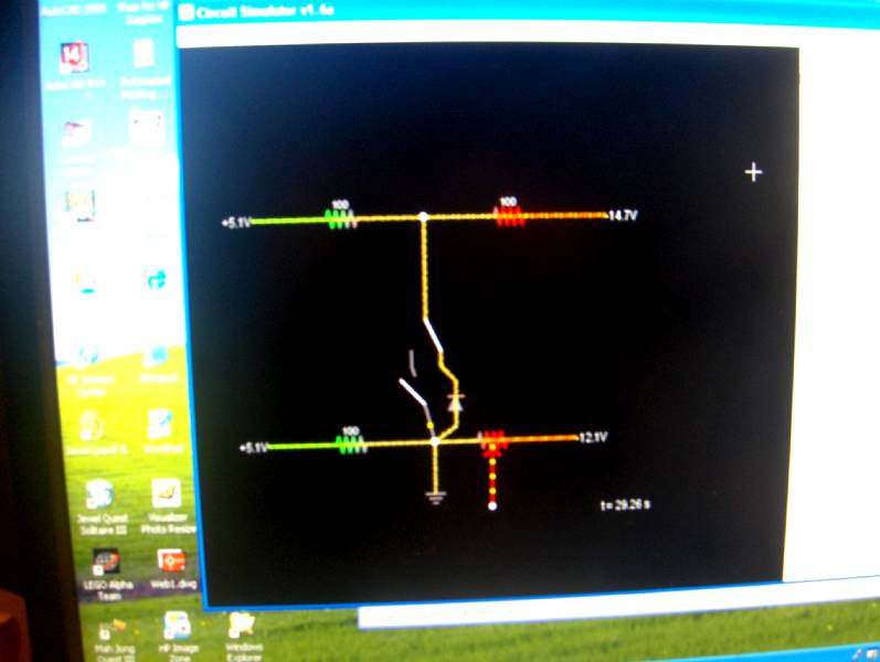
Switched Clamping Circuit – Diode Clamp, Resistor Clamp and no Clamp
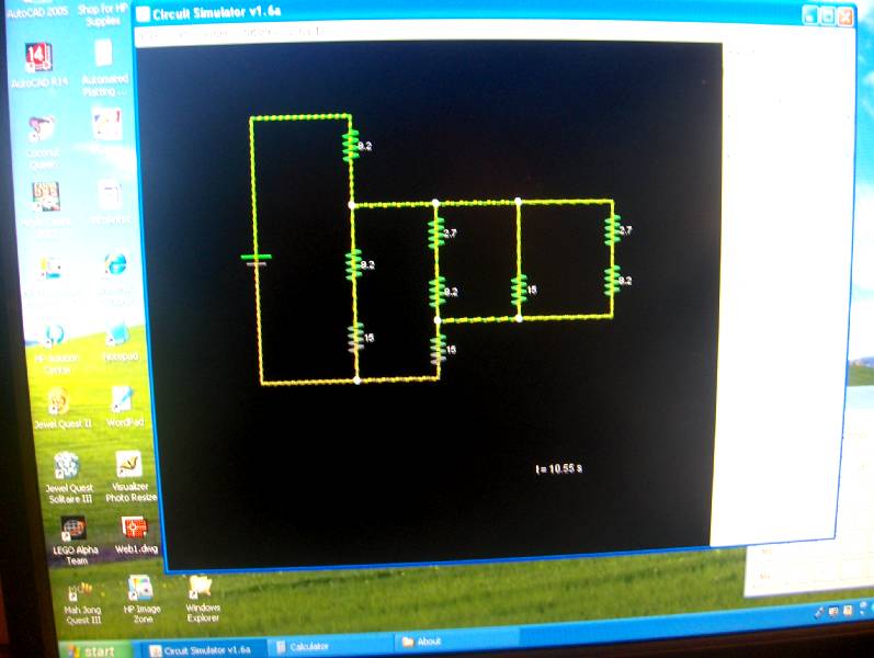
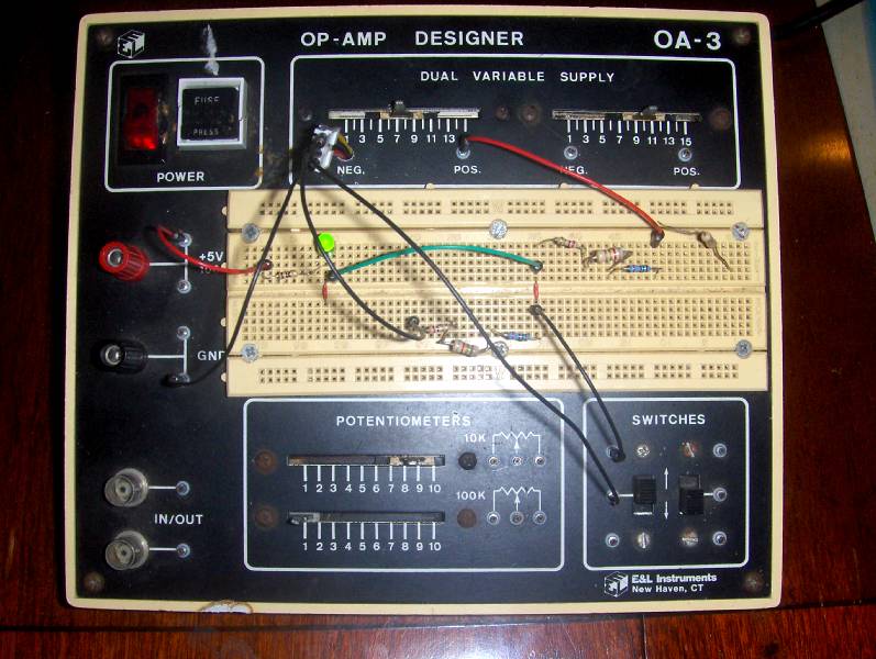
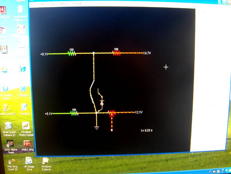
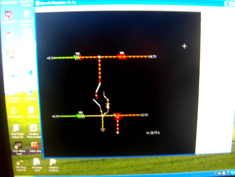
the next group of pics are of two different ‘clamping’ circuits which are each switched so i can validate the circuit without being clamped or in one of the two different clamp states. one clamping circuit is accomplished through the use of resistors and the second one with an included diode that is forward biased to the clamped circuit. the clamped circuit has a beginning node of +5.06 volts and an ending node of -14.74 volts that is divided out with two equal resistors giving a middle node of -4.84 volts. the resistor circuit that i am using to clamp that upper middle node is a similar setup with the top node at 5.08 volts and bottom node at -12.08 volts from an adjacent set of power supplies from my A/D trainer. thus i am using a separate power supply for each node. the A/D trainer has optional built-in +12 and -12 volt power supplies, but the the old E&L trainer makes you create your own. thus, you can see that i am running a positive lead from one of the variable power supplies to the stationary ground (or overall ground for the trainer) via the upper negative rail of the breadboard. each of the two variable power supplies on the E&L trainer have their own isolated negative pole which allows you to facilitate a negative voltage with respect to the overall ground of the trainer. i wanted the middle node of the second or bottom circuit to be an exact 0.0 volts so that i could readily see the clamping results. i also wanted that in order to readily see the P-N Junction voltage drop of .7 volts against the zero volt node. thus, to create the exact resistor value for the exact zero voltage result i used a potentiometer for the resistance value on the right side of the desired zero volt node. it was nice having that built-in potentiometer on the E&L trainer. that same trainer has two STDP built-in switches which i used to give me my two clamping options. as you can see by the pics i built a simulator circuit to replicate all of this. the only thing that is not totally the same is the way the switches appear in the simulator – but the results are the same as the trainer circuits that i built.
* * *
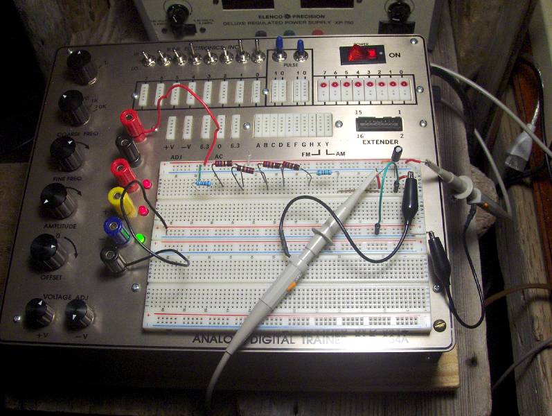
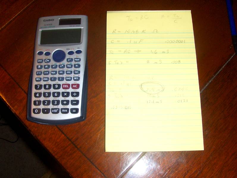
Building a RC Time Circuit
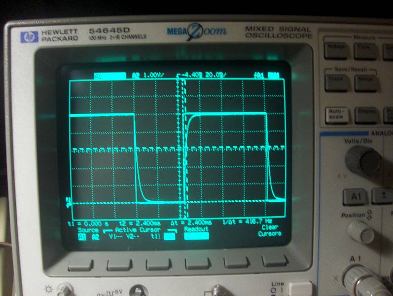
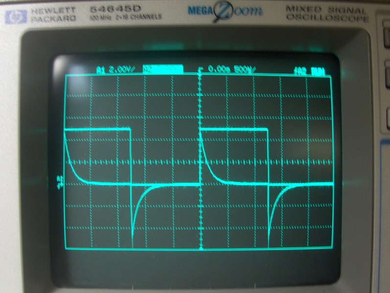
this is a major step forward on my learning curve. a capacitor is a non-linear device that sort of acts like a battery in that it can store an electric charge. thus it can have no charge or a maximum charge that is equal to the power that is supplied to the circuit that it belongs to. furthermore, it will not fill up to its maximum charge in one single swoop if there is a resistor value between it and the power source for the circuit. and the greater the resistance value that there is between the power source and the capacitor, the longer it will take to fill up the capacitor. the rate at which the capacitor will fill up is a period of five time constants. the formula for a time constant is Tc = RC which is one time constant is equal to the resistor value times the capacitor value. during the first time constant the capacitor will absorb 63.2% of its total capacity and then go back and get more. and for each of the five time constants the capacitor will absorb 63.2% of whatever room it has available. theoretically speaking the capacitor never gets completely full and keeps absorbing more and more of an electrical charge at the rate of 63.2% of whatever room it has left. but after the first five time constants, the available room that is left gets to be so small that nobody seems to care anymore. NOW – what is really Cool about this is that you can watch this all happen on an oscilloscope! And, i have one! but to get it all to happen so that you can see and measure everything just like it says in theory means that you have to really understand all the numbers involved AND Know how to use your oscilloscope! :-) AND LUCKY For Me i found some guy on YouTube who demonstrated this whole thing on an oscilloscope Just Like Mine! :-) all in all it took me a few days of futile trying this and that idea by watching other people with other types of oscilloscopes… and then another half a day to get it to actually work out right by the numbers on my oscilloscope after i found this last guy. but when it all worked out and i was actually understanding it… that was time to celebrate! and celebrate i did! thus the pics below of me making pop corn on the stove! :-) if you look closely at the first pic you can see the line that curves to the right down at the bottom a couple of times and once at the top to the right in the middle of the other two that curve. sooo, actually what is happening is that below where it curves it is a straight line that has veered off to the right and the closer it gets to a straight horizontal line the veering straight line becomes a curve and then dies out into another straight line. so the vertical line before the curve going down or up is it either filling up real fast or discharging real fast. then the curve is where it slows down filling or discharging. and the horizontal straight line is it either filling up or discharging so slowly it looks like a straight line again. the other vertical and horizontal lines are what it would be doing if there was not capacitor in the circuit. all them heavier dashed lines are the cursor lines on the oscilloscope that let you pick when and where you get to take your measurements. with the vertical up and down directions you are measuring voltage – with the horizontal back and forth directions your are measuring time. pretty cool eh? * * * 1/16/14 -> i just learned that the RC circuit that i was practicing on and that is pictured in the first pic below is called or referred to as an integrator circuit and its waveform is developed over the capacitor which follows a resistor in the circuit. there is also what is called a differentiator circuit where the resistor follows the capacitor with the waveform being developed over the resistor. a pic of that waveform is pictured below after the popcorn pics! :-) BTW in both of these RC waveform pics i am using a two channel presentation which shows the RC circuit superimposed over a square wave of (0v & +5v) in order to demonstrate the charge and discharge volts versus time activities of the capacitor through its time constants.


* * *
Stepping up to a Function Generator
yep aroo! a Function Generator! …ahh, a what? :-) well, electricity doesn’t just turn light bulbs on and off, but it can make interesting pictures also.
actually, one of the important aspects about electricity is voltage, and you can measure that pictorially on an oscilloscope. an oscilloscope does this by representing voltage on a graph. up and down on the graph (vertical graduations) is the amount of voltage… back and forth on the graph (horizontal graduations) is the duration of the voltage in terms of time. so, if you have a constant amount of direct current voltage running though a circuit, then you would just see a horizontal line going across the oscilloscope screen. however, if you had a constant amount of alternating current voltage running though a circuit, then you would see a wavy line going across the oscilloscope screen in the form of a sign wave. many computer circuits operate on voltages which are either close to zero volts or five volts (a low voltage signal or a high voltage symbol). thus, the one’s and zero’s of computer logic are symbolized electronically by either low or high voltage impulses or signals. therefore, on an oscilloscope, a pattern of one’s and zero’s would show up as horizontal line which alternates at either the low voltage or the high. if these alternating signals are a repetitive zero, one, zero, one, zero, one…. then you would see what is called a square wave on the screen of the oscilloscope. a function generator is a device that will emit these now described signal patterns, the square wave, the sine wave and as well other kinds of signal patterns. having such a device allows you to do testing with such signal patterns according to various design goals.
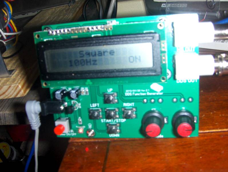
being as i am a beginner, i was needing a function generator so i could get familiar with these various signal patterns and how to view and use them on my oscilloscope. the first two photos below show my first function generator that i got from China via ebay for only $23 including shipping! how somebody can make something like this and then mail it to me all the way from China for only $23 is beyond my comprehension. but not long after i received it i broke it by using an incorrect power supply on it (center ground rather than center positive). at that point i decided to get a better function generator that could produce frequencies below a 100 hz as well as produce a cleaner signal. in the first photo you can see that the horizontal line of the square wave is real fuzzy looking. that is because the signal has a lot of noise on it. the second photo is the actual function generator.
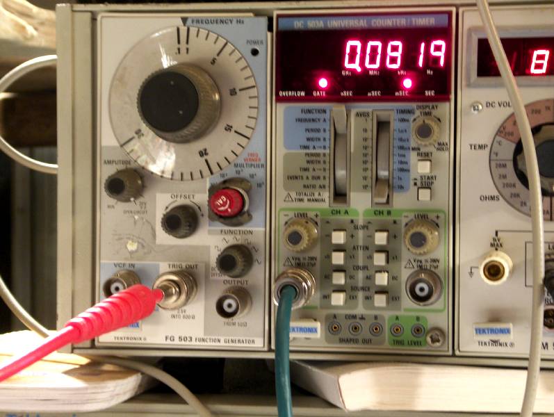
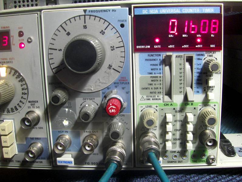
so i ended up buying some older 1970’s Tektronix equipment which includes an FG 503 function generator. in the third photo you can see how much cleaner the horizontal lines of the square wave function appear relative to the first photo. that last photo shows the actual function generator as well as a Tektronix DC 503A Universal Counter Timer. what is nice about that last photo is that all three pieces of equipment are all agreeing with each other. you can see that the oscilloscope is showing a time measurement of 16.08 hz and that the Frequency Counter is showing 0.1608 Khz for the square wave being emitted by the function generator! pretty cool.
ps – i was able to fix the first function generator by replacing a little 78L05 voltage regulator.
* * *
Fun With LED’s
All LED’s are Not Created Equal. i found a lot of help online about how to drive LED’s with small circuits – either in series or in parallel. basically the info runs along the lines about the fact that most LED’s require 2-3 volts and should be in series with a current limiting resistor in the range of 100-200 ohms. well… i found that is ‘sort’ of correct, but it leaves a lot up in the air depending upon the actual requirements of the LED. so far i have messed with ten different LED’s and found nine different sets of requirements. thus, i ended up experimenting with them and coming up with my own list of datasheets for all my LED’s. that way, when designing a circuit that includes one or more LED’s i can have a reasonable expectation that the circuit will actually work. one of the biggest things i discovered is that none of the LED info ever includes how much resistance an LED will add to a circuit. i have found through detailed experimentation that differing LED’s can generate anywhere from as little as 89 ohms of resistance to as much as 157 ohms. the approach that i used for my experimentation was to use a nominal amount of resistance (six ohms) and drive the LED from a variable power supply while using an ammeter in order to adjust the voltage till i was seeing 20 mA. this way i could get a pretty good fix on the voltage drop for that particular LED. i figured this to be a good approach because the only consistent documentation i have noticed about LED’s is that they are happiest when stimulated with 20 mA. then, to prove out my experimentation, i would build a circuit using three of that type of LED and drive it with a voltage known to be in excess of three times of the acquired VD amount learned from the first test. then i would insert a variable resistor at the end of the circuit and adjust it till the ammeter reading gave me a 20.0 or 20.1 mA reading. this would allow me to then ground out the circuit and reliably check VD readings for each individual LED as well as their summation. this approach proved to produce very reliable data which i could then use to mix and match LED’s, precalculate voltage and resistance needs and get a good circuit. furthermore, doing this required that i constantly think everything through all the time, record my data and then be able to look back at the data to validate my learning curve. this was very good experience for me to be constantly refining everything down to the tenth of a mA, a tenth of an ohm and even down to the hundredth of a volt (tens of a millivolt). doing all of this allowed me to gain a lot of electrical confidence which is very important because i could then actually see the knowledge coming alive. i have found that acquiring confidence in things like ohm’s law is difficult because so many of the components have such relative tolerance levels, and that often leads to real circuits not performing equal to your calculations. this can be a frustrating experience because without good validation, it is hard to know if the problem is because of variations in the components or the understanding that you are working with is faulty. AND! i have found that a really Big Bonus to my learning curve has been in the acquisition and use of VARIABLE resistors. i have been using the Bonens 3296 precision trimmer resistors with Great Success in these experiments. they offer so many convenient ranges and have the very useful bread board spacing to their through hole pin design. before finding and using these i would sometimes have a very confusing number of 1% resistors laying around all over the place. so now, stand alone resistors are a thing of the past unless one of my prototype circuits start to become finalized.
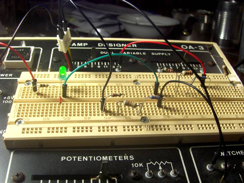
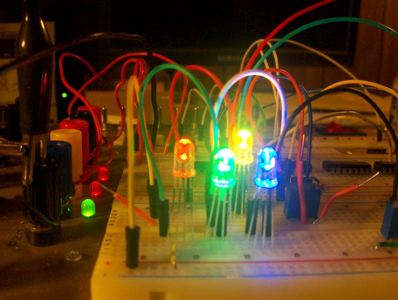
the real bonus to these LED experiments has come from playing with the four pin Red-Green-Blue LED’s. i built datasheets for each cathode pin of the LED (there are three cathodes for each LED). then i was able to wire each pin in a series circuit in order to prove the data by the combined VD’s and in circuit resistance values of each pin (color). THEN, i wired up the Red and Green cathode pins with a Bonens trimmer resistor in each path to ground for the two pins. this allowed me to adjust the current through each cathode in such a way that allowed me to actually get the resulting Yellow colored light. this was most gratifying. thus below you can see how i wired three of those RGB LED’s in series and thereby getting the appropriate colors. AND behind those three lights you can see that i was able to actually get the yellow light from using the Red and Green cathodes. these are the super bright LED’s, so i had to turn the amperage way down in order to take a picture without blinding the camera.
* * *
My First Actual Project
after spending time leaning about Ohm’s Law and resistors, diodes and transistors i felt that i could/should know enough to design my first actual project that did something i wanted done. this happens to be a control box that switches my PC speakers between different PC’s. i have this KVM switch that allows me to access four PC’s with only having to have one keyboard, one mouse and one LCD monitor by just hitting a button in order to go from one PC to the next. however, unless you get a more expensive KVM switch, they typically do not have a central place to plug in your speakers so that when you are ‘present’ with a given PC you also have the speakers activated for that PC. so my first project has to do with making a small control box that allows me to switch one set of PC speakers between any of my four PC’s.
the task by itself can be done quite easily by just just creating a small board that has four sockets that accept the mini stereo speaker plugs from each PC, and then make them switchable to a socket that accepts the actual speaker mini stereo speaker plug. and all you would have to do is wire the four PC sockets to a four position SPST (single pole single throw) switch. however… :-) i was wanting to be more creative than that. i was wanting some nifty LED action that told me by looking at the control box just exactly ‘which’ PC was the current PC that was active with the speakers! :-) sooo… that meant having that four position switch be a DPST (double pole single throw) switch so that each position of the switch could also control the nifty LED lights.
two main choices came to my mind on how to have which computer was active for the speakers by LED lights. one choice would be to use a seven segment digital display saying that the current PC was PC number 1 or 2 or 3 or 4. but that sounded WAY beyond my skill level and that the idea of just having four LED’s with one LED lighting up when PC number one was active, and two LED’s lighting up when PC number two was active and so on sounded like it would be much easier to design. but after i got into trying to do that it became quite a difficult task to only have four LED’s and have them alternately light up so that they indicated which of the four PC’s was the active PC. if i had four banks of LED’s with one bank only having one LED and the second bank having two LED’s and so on, then it would have been real easy to wire that up. but noooo… :-) i had to have just four LED’s which meant that each position of the switch would turn on and off the appropriate number of LED’s so that i would see just one LED or two or three or four LED’s lighted up (in their proper order) to indicate which PC was active!
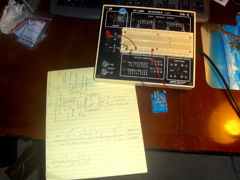
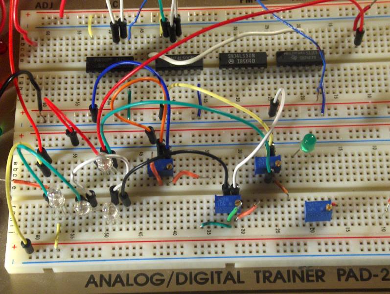
sooo… over the past few months i have bought parts and thought up various schemes about how to do that after each little learning curve in my electronics learning path. at one point i was playing with little circuits that made use of 74LS08 IC AND gates, and using transistors to go between the 5V signals of the 74LS08 and the projected voltage needs of powering one, two, three or four LED’s along with the various resistor needs for current limiting the various combinations of LED’s and so on. but when it was all said and done, i ended up just having to use some well placed small signal diodes for controlling the individual LED choices from each position of the switch. and after it was all worked out and working it all made perfect electronic sense – but getting my mind to think in terms of electrical functionality was a much bigger challenge than i had anticipated. :-) which is what ‘learning curves’ are all about! so it has been quite fun to just be able to hit little switches and see the appropriate lighting scheme actually happen. so the four pictures below show my prototype circuit for controlling the appropriate lighting of the LED’s.
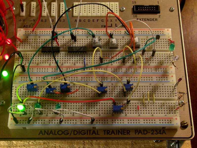
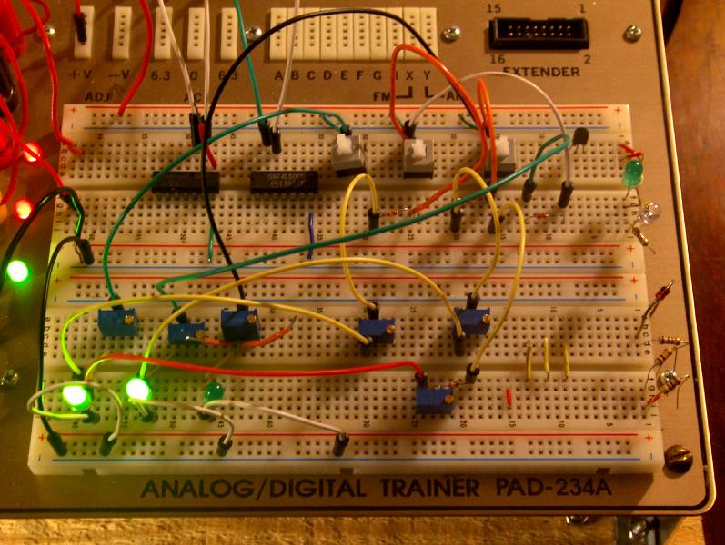
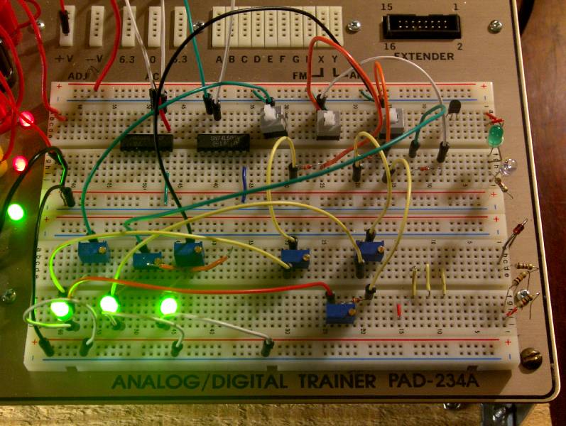
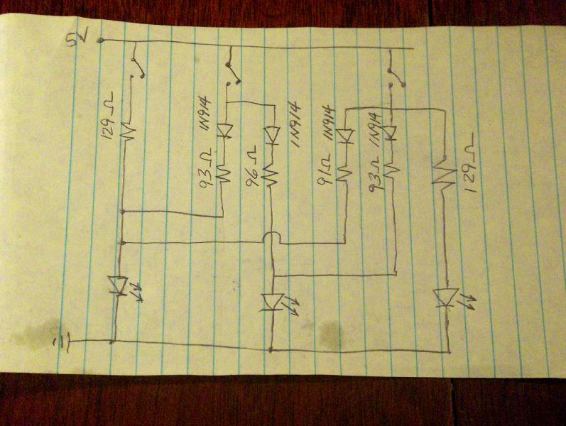
my next step in this process will be to design the actual circuit board layout with the sockets and the switch and the LED placements. as i do that i will take pics that show the whole thing coming together. in these current pics you will notice that i am using six trimmer resistors in order to get all the appropriate mA flows happening to the various LED’s at their various times of being lighted by the various contact points of the switch. i am finding that i LOVE trimmer resistors because they allow me to ‘play’ with current flow instead of having to ‘calculate’ current flow at various points within the circuit. what i found challenging was the fact that at times i was having to current limit a given LED either with or without a signal diode voltage drop in the path. and because of my inexperience i kept underestimating when i needed a diode in order to block current flow from one LED to another because it was wanting to flow backwards to an adjoining LED. and… like i already said… once i was all done and had a working circuit, it looked so simple and logical because i had four LED’s, four diodes with their four smaller resistor values! :-) it makes me laugh when i look at in now, but the path to figuring it out so it actually worked was a number of days of experimentation and failure and head scratching because this LED would light and not that one and so on. and… you will notice that this prototype circuit only shows the needed process for lighting and controlling only three LED’s. but that is because controlling these three represent controlling the LED lighting requirements for LED’s #2, #3 and #4. LED #1 is going to be controlled in the actual circuit as being lit at all times because either of the four switch positions would require that it be always lit. so, in my mind that light is also going to double as the power ‘on’ indicator LED light.
* * *
Scope’n Out My DIGI Designer
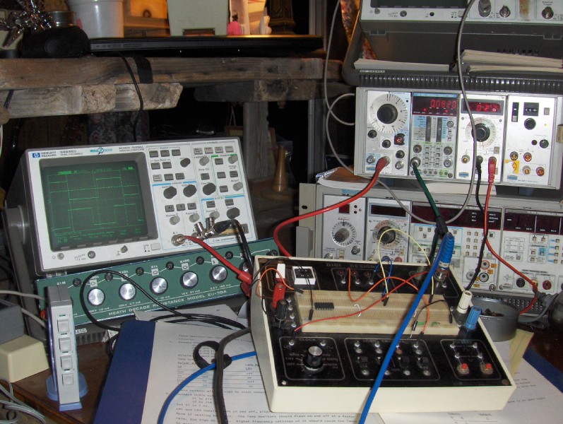
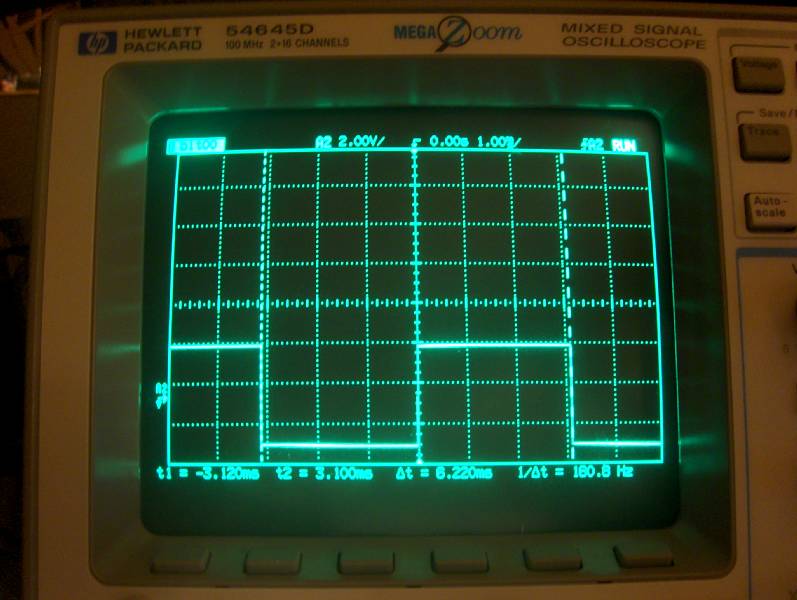
i have started giving more energy/time to electronic digital logic. i have this mid 70’s trainer that was intended as a self teaching apparatus for this purpose. it is called a DIGI Desinger. it was created and sold by E&L Instruments out of Connecticut. there are a couple of texts that go along with its use that implement 74xxx TTL logic chips for the purpose of learning such things and inverter circuits, latching, flip flops, bus data decoding and so forth. in gearing up for using the trainer and its various electrical functions i was using the BnC connectors for input and output to output to my oscilloscope and checking the accuracy of the square wave clock frequencies that are provided by the trainer for experimental purposes. this was a good experience for me because it was an opportunity to become more familiar with the use of my oscilloscope. in doing so, i decided to compare the accuracy of and the quality of the square wave form to that which is generated by my function generator. i have this really nice Tektronix setup which has a FG 503 Function Generator along with a DC 503A Universal Counter/Timer. so, i spent quite an amount of time going back and forth between the DIGI Designer, my oscilloscope and these two Tektronix devices. i found that i could use the DC 503A as a frequency counter to calibrate and adjust the square wave function that the FG 503 was triggering. then i could also, simultaneously send that wave form to my dual trace oscilloscope. that allowed me to also send (supposedly) the same frequency wave form to the other channel of the oscilloscope for a comparison. in doing so, i found that the DIGI Designer’s wave form frequency was not very accurate (which i do not think really matters for the isolated experiments that i will be doing with it). but it was a GREAT learning experience for me in using and becoming much more familiar with my test equipment – and for that i am quite grateful and more excited about what i am doing. it is one thing to buy this stuff and another whole other deal to actually use it. since i have been collecting all this stuff i have often wondered if actually using, learning and doing would be appealing, or if it was just some fantasy. but, gratefully, i am finding that i actually do enjoy progressing with the application and understandings that are coming with the learning experience.
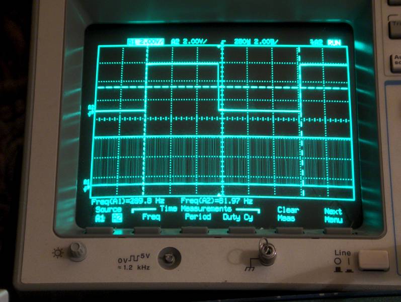
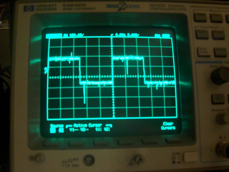
the pics below are of me using the equipment as i have just explained. you can see that channel A2 of the oscilloscope is agreeing with the digits that are being displayed by the frequency counter. channel A2 of the oscilloscope is reporting a frequency of 81.97 Hz, and the DC 503A is reporting 0.0819 Khz. (0.0819 Khz x 1000 = 81.9 Hz)